Furnace Replacement Component
A component in the heat-treatment furnace broke. Using the damaged part itself as the only reference, I measured it, recreated its geometry in CAD, and supported manufacture of a machined replacement.
- Component
- Bearing component from the heat-treatment furnace
- Reference
- The broken original part — no drawings available
- My role
- Measurement, CAD reconstruction, manufacturing support
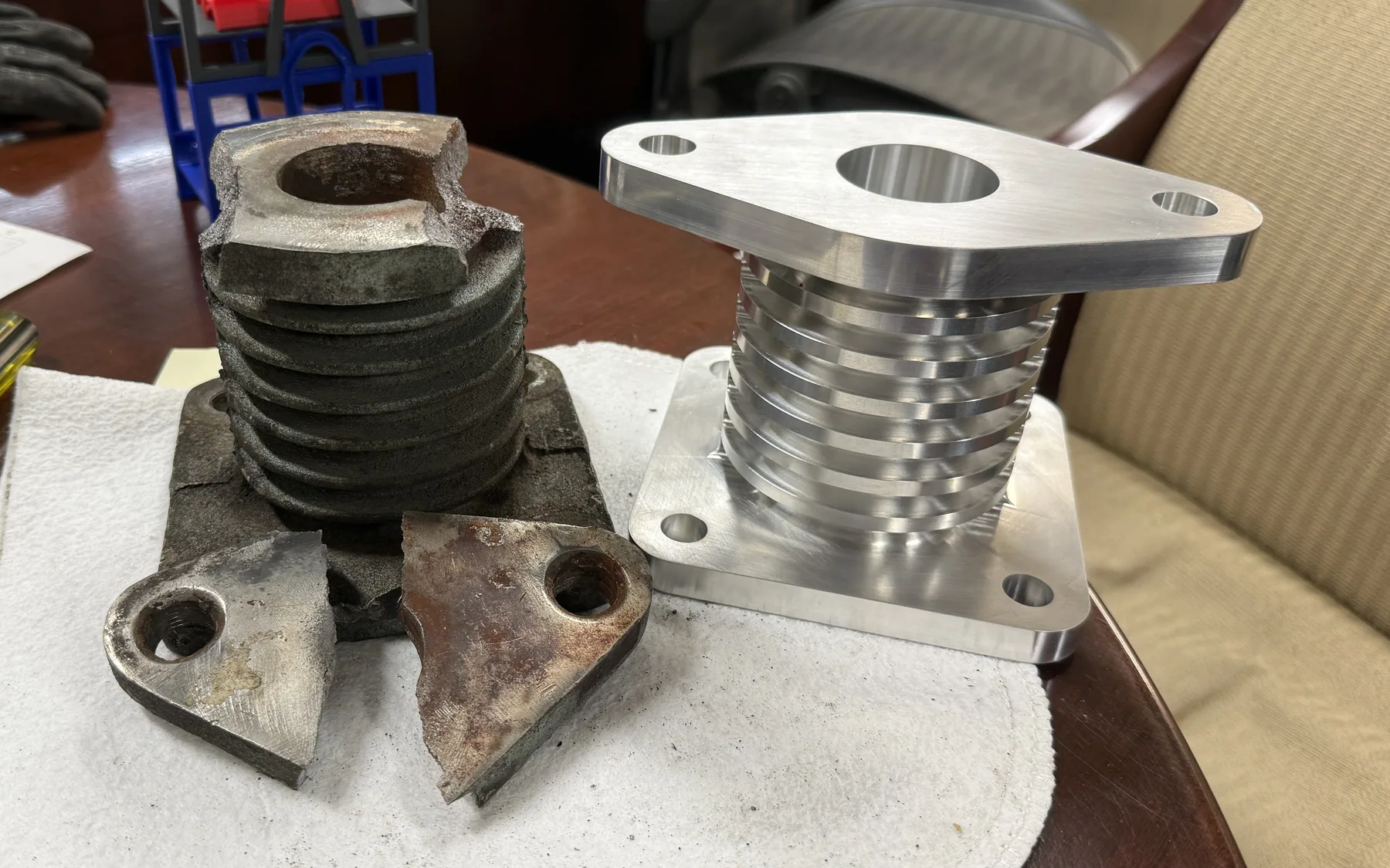
Broken part to finished replacement
The sequence here is the whole project — each step could only start once the one before it was right.
Problem
A component in the heat-treatment furnace failed, taking the assembly out of service.
Measure
The damaged part measured by hand, working around the worn and broken faces.
Design
Geometry recreated in CAD and modeled to the dimensions the replacement needed to hold.
Manufacture
A new component machined from the model.
Result
A finished physical replacement for the broken original.
No drawing, one broken sample
Reverse engineering a failed part is harder than measuring a good one. The reference is damaged in exactly the places that matter, so some geometry has to be read from the surfaces that survived and inferred from how the part sits in the assembly.
I worked from the physical component: measuring the damaged part, recreating its geometry in CAD, and modeling the replacement to the dimensions it needed to hold so a new part could be manufactured to take the place of the broken one.
What I learned
- Decide what the part must control. Not every measured surface is critical; identifying which ones actually locate and load the part is most of the work.
- A broken part is still evidence. Wear patterns and fracture surfaces say something about how the component was loaded.
- Model for the process that will cut it. Geometry that is trivial to draw is not always trivial to machine.