Custom FPV Drone — Airframe & Electronics Integration
An in-progress custom FPV quadcopter, built up from a bare carbon-fiber frame. The work so far has been turning a bench full of separate mechanical and electrical parts into one integrated airframe — motors mounted, flight-control electronics installed, and every motor and power connection soldered and routed by hand.
- My role
- Builder — component layout, mechanical assembly, soldering, wiring, and integration
- Status
- In progress — integrated airframe and electronics; not yet configured or flown
- Process
- Components → airframe & motors → electronics & power → soldering & routing → configuration & testing (next)
- Configuration
- Quadcopter — carbon-fiber frame, four brushless motors, central flight-control board
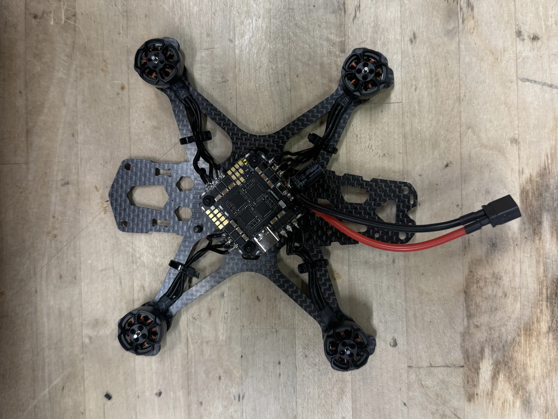
Status note: this is an active build. This page documents it through the hardware-integration stage — the airframe, motors, electronics, and power wiring are assembled and soldered. The flight controller has not been configured and the aircraft has not flown. The page will be updated as the build moves through configuration and testing.
From separate parts to one system
Four stages complete so far. The fifth is next.
Components
Every part laid out and accounted for before anything was fixed to the frame.
Airframe & motors
Carbon-fiber frame assembled and four brushless motors mounted at the arm tips.
Electronics & power
Flight-control board mounted centrally, with the battery lead and capacitor soldered in.
Solder & route
Motor leads trimmed, soldered to the board, and secured along the arms.
Configure & test
Configuration, system checks, and first controlled testing. Not yet started.
A compact electromechanical system
A small quadcopter is a dense electromechanical system. Four motors, the electronics that drive them, the flight controller, and the battery all share one compact frame, and every one of them is joined to the others by wire. The mechanical layout decides where the wires can go, and the wiring decides whether the layout actually works.
I'm building this one up from the bare frame. The end goal is a working FPV aircraft, but the engineering so far has been integration: getting mechanical hardware, power electronics, and wiring to fit together cleanly and reliably, in a way that can still be worked on later.
The project is still in progress. What follows covers the build up to its current stage, where the airframe, motors, electronics, and power wiring are assembled and soldered into a single unit.
Seeing the whole system before building any of it
Before anything was fixed to the frame, I laid every component out on the bench: the carbon-fiber frame plates, the four motors, the flight-control electronics, the camera, the antenna, the battery, the power lead, and the bagged hardware for each subassembly.
Seeing it all at once made it easier to work out what had to connect to what, and to think through the order of assembly — which parts go on the frame first, what becomes hard to reach once the next layer is installed, and where the wiring from each component will have to travel.
At this point it is a collection of separate mechanical and electrical parts. The rest of the build is the work of turning that collection into one system.
Frame and motors
The carbon-fiber frame came first, then the four brushless motors at the ends of the arms.
With the frame plate assembled, I mounted the four brushless motors at the arm tips and placed the central electronics board on the frame. This was the first point where the build existed as a physical system rather than a set of parts, and the first point where the packaging problem became real.
Each motor has three phase leads, and at this stage all twelve were left full-length and loose. They stayed that way until the board's final position was settled, since a lead cut too short cannot be recovered and every lead's length depends on where its pad ends up.
The mechanical concerns here are the ones that apply to any rotating hardware: motors seated squarely on the arms, fasteners secure, and nothing positioned where it could end up in the path of a propeller.
The electronics board and the power input
The central board carries the flight-control electronics and the pads the motors are driven from, so it is where every connection on the aircraft ends up. It sits in the middle of the frame on four grommeted mounting screws, which keeps it on the aircraft's center line and gives all four motor runs a similar path back to the board.
Power comes in through a single battery lead soldered to the board's power pads. Alongside it is an electrolytic capacitor, rated 35 V and 220 µF, soldered to the same input. A capacitor in that position is standard practice on this kind of build: it helps absorb the voltage spikes and electrical noise that the motor-drive electronics put back onto the supply.
The battery lead is the heaviest-gauge wire on the aircraft and carries the current for all four motors, so these are the joints where a weak connection matters most. Working on the board off the frame meant it could be held flat, with clear access to the pads.
Soldering the motors in
With the board in its final position, the motor leads could be cut to length and soldered.
Each of the four motors connects to the board through three phase leads, which makes twelve motor joints on top of the power connections. Every one of them lands on a small pad beside its neighbors, on a board with components packed closely around it.
The practical concerns at this stage were:
- Sound joints. Solder fully wetting both pad and wire, since a marginal joint on a motor phase can pass a quick look and still fail under vibration.
- No bridges. Adjacent phase pads sit close together, and a stray bead of solder between them is a short.
- Lead length. Each lead trimmed to reach its pad without a long loop of spare wire, while leaving enough slack that the joint is not under tension.
- Routing. Leads kept close along the frame arms and clear of the propeller arcs, then secured with cable ties.
- Serviceability. Joints left accessible from above, so a motor can be desoldered and replaced without taking the rest of the electronics apart.
It is the least visible part of the build and the part the rest of it depends on: all of the power and every motor command pass through these joints.
Integrated airframe and electronics
The build has moved from a layout of separate parts to a single assembled unit.
The current assembly brings the carbon-fiber frame, all four brushless motors, the flight-control board, and the battery lead together as one unit. The motor leads are trimmed, soldered, and secured to each arm with cable ties, and the battery lead is soldered in and exits from one end of the frame.
Comparing it with the earlier fit-up also shows a layout change. The board ended up rotated a half turn from its first position, which moved the power pads and capacitor to the other side and changed where the battery lead leaves the frame. Placement decisions like that tend to settle only once the real wires are in hand and their routing can be seen.
This is an integration milestone, not a finished aircraft. The flight controller has not been configured, and the drone has not flown.
What comes next
The remaining work, roughly in order. None of it has been done yet; this page will be updated as each stage is completed.
- Complete the hardware. Install the remaining components from the original layout, including the FPV camera, and finish assembling the frame.
- Verify the electrical work. Inspect every joint and check the power input for shorts before the system is powered from a flight battery.
- Configure the flight controller. Firmware setup, motor order and spin direction, and the control link.
- System checks. Bench testing with the propellers removed.
- Initial controlled testing. Short, controlled first flights in a safe environment.
- Tuning and refinement. Iterating on the setup based on what testing shows.